
Blog
Perhaps you’re keeping your horses out 24/7 with only a field shelter and a port-a-cabin. Or maybe your yard has a full range of buildings but no mains electricity. Either way it remains that the challenges of having no electricity can be difficult.
From lighting and clipping through to providing power for the visiting vet, having a reliable power source is both convenient and essential. There are many solutions other than running mains power to the area. This could be installing a diesel or petrol generator, solar panels, wind turbines or one of the many other myriad of possible solutions.
In some ways a generator can be the most reliable solution. Once setup the only day to day chore is to keep it topped up with fuel and turn it on when you need it. However there are some negatives. Firstly they’re very noisy and if we’re honest ruins the peace and tranquility that often comes with remote locations. Secondly having to manually turn on the generator when all you need is one light to mix up some feed or find a piece of tack can be a pain. Finally there is the cost. Petrol/diesel being the price it is these days means that the fuel to run it adds up quickly and thats before you have to do pay for any ‘unplanned’ repairs. You also need to perform the routine maintenance such as oil changes when needed.
At the other end of the spectrum there is solar/wind power. It has the benefit that the ongoing costs are minimal, as instead of continually adding in more fuel the ‘power’ comes from the environment. In the case of solar it even does this without making any noise at all. You’ll also be getting on the renewable energy train which has got to be worth some extra brownie points from an environmental point of view. The downside is that it’s not always reliable, if the winds not blowing or the suns not shining (a definite possibility in the UK) the ‘power’ going in from the environment might not meet the need you have for power at the yard.
A member of our team recently volunteered to help out a small stables in this exact situation. The aim? An off grid, reliable supply of energy for lights thats as convenient to use as mains electricity. Sounds good? Well read on.
Firstly let us add the much needed ‘required disclaimer’. We’re not professionals in this area. So don’t take anything we write here as certain. We just wanted to share what we’d learnt as a way of helping you on your journey. But if you’re not confident consult an expert.
With the overall goal decided we needed to work out what we’d needed.
We needed to be able to provide light to 3 stables and the outdoor areas for about 2.5 hours a day (an hour in the morning before the suns up and an hour in the evening to complete all the daily chores + a bit spare).
We’re going to light everything using outdoor rated LED strip lights and for the stables this meant we needed about 12.5 meters of LED strips.
Something like these (x 3): https://www.amazon.co.uk/Waterproof-Daylight-Striplight-Outdoor-Lighting/dp/B00HSF66JO
The spec sheet lists that they use around 3.6 watts per meter. So it means we’ll be using 45 watts if we wanted to power them all up a the same time. However generally only half will ever be on at a time so 22.5 watts. If we’re running them for 2.5 hours a day that equates to 56.25 Watt Hours a day. This is the number we need to ensure that we can a) generate each day b) store in a battery during the day time ready to be deployed back at night time.
We decided to go for solar power. It’s relative simple installation and affordability were the deciding factors. We looked for a solar power kit that would come with a panel, connecting wires and an appropriate controller to hook it all together.
We choose a kit a bit like this one https://www.amazon.co.uk/dp/B010FLW6DC
We also needed some additional wiring to connect everything together, some fuses (because fuses are always a good idea), a battery and the lights themselves.
Ok, so there is some maths. To be honest we just guessed it would be ok and have gone back and done the calculations since. However if you’re worried about making sure things work first time for your needs it’s probably a good idea. However if you like to live on the wild side and just ‘wing it’ feel free to skip to the next section.
The kit provided us with a 100 watt panel. Note: this is how much power the panel generates in an optimal situation which is never the case. There are a number of things which can effect the power you’ll get: panel positioning, type of charge controller, panel angle relative to the sun, time of year.
Considering winter is when the lights will be most needed and is also when the panels receive the least amount of usable light, we’ll do our calculations based on this. We reviewed various sources and found that the usable solar generating hours a day can get as low as 2 hours. For argument sake lets say the efficiency of our system is about 60%. This number can change a lot but this seems like a good starting point.
So with these assumptions in place we can estimate that we’ll get 120 watt hours per day (100 watts * 0.6 efficiency * 2 hours). As this is greater than our estimated use of 56.25 watt hours per day we should be ok with our 100 watt panel and have some to spare (always good so we can try other things in the future).
The final thing we needed to calculate and consider is our panel mount angle. For this we went to the great site at https://www.solarpaneltilt.com/ . You can work through it for your own setup. This yard is based in the south of England (latitude of about 50 degrees) and as we’re optimising for the winter months (so we’ll pretend we’re adjusting the panel twice a year but we’ll most likely just leave it in the ‘winter setting’) it works out to be an angle of around 60 degrees relative to the ground and pointing south.
There are numerous types of battery setups to choose from. From Lithium Ion Cells (like they use in electric cars) through to old ‘traditional’ car batteries. They all have their advantages and disadvantages. However in this setup we have the benefit that what we need from the battery is quite minimal and space is not really a problem. So we chose our battery type based on overall cost.
Because of this we chose a Lead Acid Battery. Even within this type of battery there are a huge range of ‘sub types’. The type which is most likely the best for this situation is what’s called a ‘Deep Cycle’ battery. This battery is designed to allow you to drain more out of the battery without damaging it (https://en.wikipedia.org/wiki/Deep-cycle_battery). If you’re buying a new battery for the project we recommend looking at one of these.
However something most equine people seem to have a lot of is old car batteries (we all need to power the electric fence! Right?). These are not ideal batteries for the job as they don’t like being discharged much and if you do they get damaged over time. As we’ve said the demand on the battery is quite limited. Because of this we can normally get away with it. This is what we did to start with and it worked ok (we did end up changing it in the end to one of these https://www.eurocarparts.com/ecp/p/car-parts/car-body-parts-and-car-exhaust/exhausts/heat-exchanger/?444776773 as the battery was very old and wouldn’t hold a charge. However this speaks more to the condition of that specific battery rather than the idea of using an old car battery overall).
Right, now we’ve done the boring bits lets get started! We mocked up a rough 3D representation of our panel so we could visualise what we’re doing and experiment with various mounting approaches.
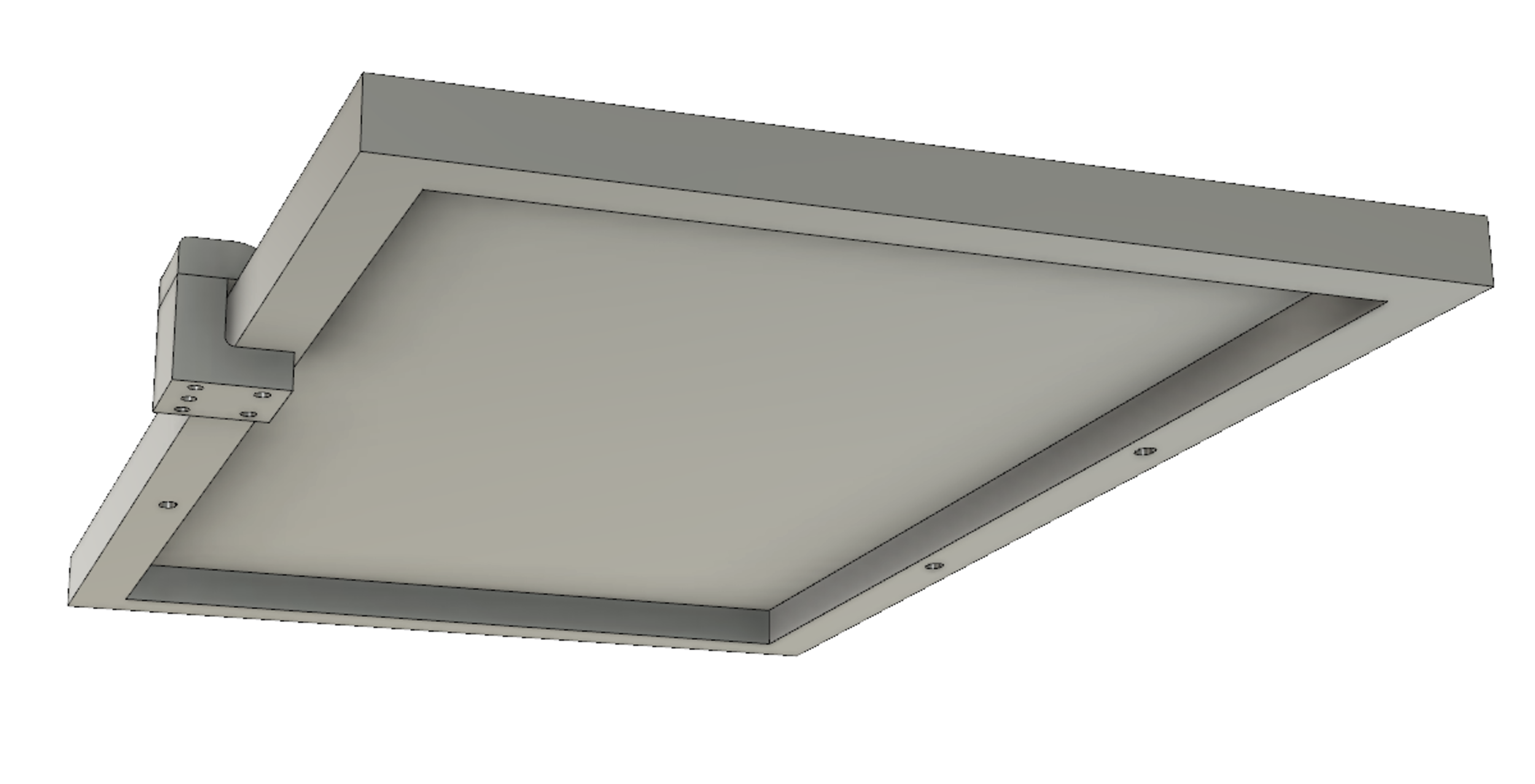
In the end we decided to mount some wooden battens to the roof and then use that as a point to attach everything to. Next we built a simple wooden frame that would hold the panel at 60 degrees relative to the equator (as per the solar mounting website). Then we bolted the panel to this frame and lugged it onto the roof and attached it to that.
With all the equipment acquired and the panel in place we then set everything up. Below is a rough wiring diagram of the overall system. As you’ll see the wiring in concept is actually quite simple. It can begin to look a bit messy in reality once you’ve added lots of different lights but so long as you keep it organised it’s not too bad.
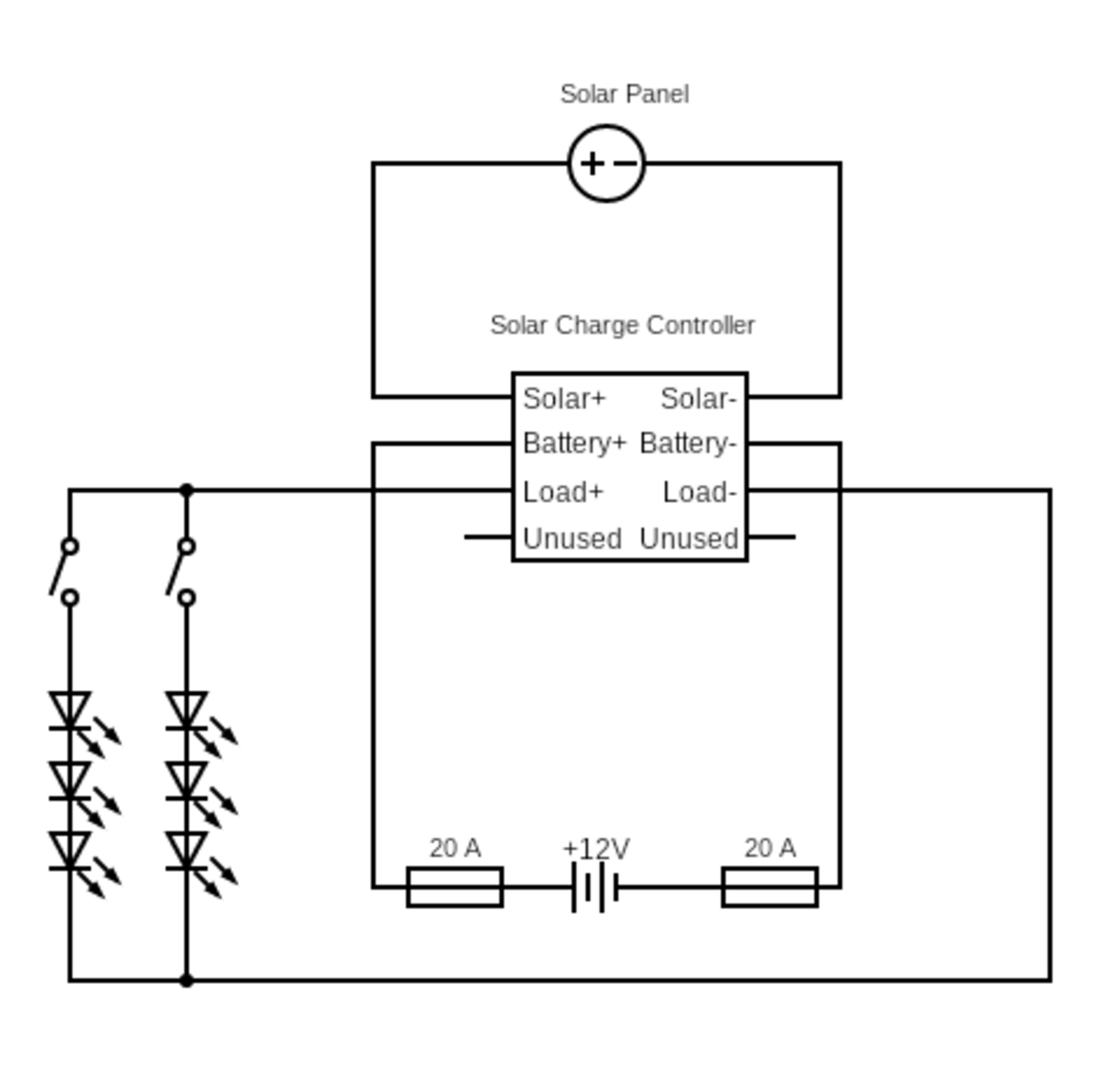
The controller should be located near the solar panel, the battery and ideally the lights.
There are three sets of wires that need to feed into the controller; the battery, the solar input and the load (the lights). We’ve run each of these into an individual isolator switch which allows us to isolate any part of the system to allow us to work on it. The battery is also connected with a fuse on both the positive and negative terminal. This should protect the system if the battery is ever shorted up stream.
The kit came with some specialist solar cable which on one end is stripped and connected to the controller and at the other end is terminated in a solar connector which can plug into the panel. Please note: it’s advised to cover the panel with an opaque material when making any connections. This is because the panel is generating electricity when exposed to light and there is a possibility of danger when connecting it whilst it’s doing so.
Finally the load is connected up to some sort of power distribution block (we used terminal strips as our current/voltage requirements are relatively low - but ensure you check this.)
On some systems it’s advised that you ground the panel and other components - our panel suggested that this was not necessary for a 12V system but we’re planning on doing it anyway for extra peace of mind.
A requirement that we wanted to meet was for turning a light on to be as simple as flicking a switch like you would with a mains powered system. So we decided that we’d run a connection to each light from our distribution block with it’s own switch. This kept our wiring very simple (if not the most efficient use of wire) and meant we could just repeat it for each new light we needed.
We looked at available boxes for the switches on the market but decided we’d build our own (mostly as we wanted an excuse to use the 3D printer). We purchased a waterproof version of a switch like this https://www.amazon.co.uk/Sunerly-Trailer-Illuminated-Rocker-Switch/dp/B072PY65Z8 and then designed a couple of boxes in Fusion 360, to house the switches, which were then 3D printed.
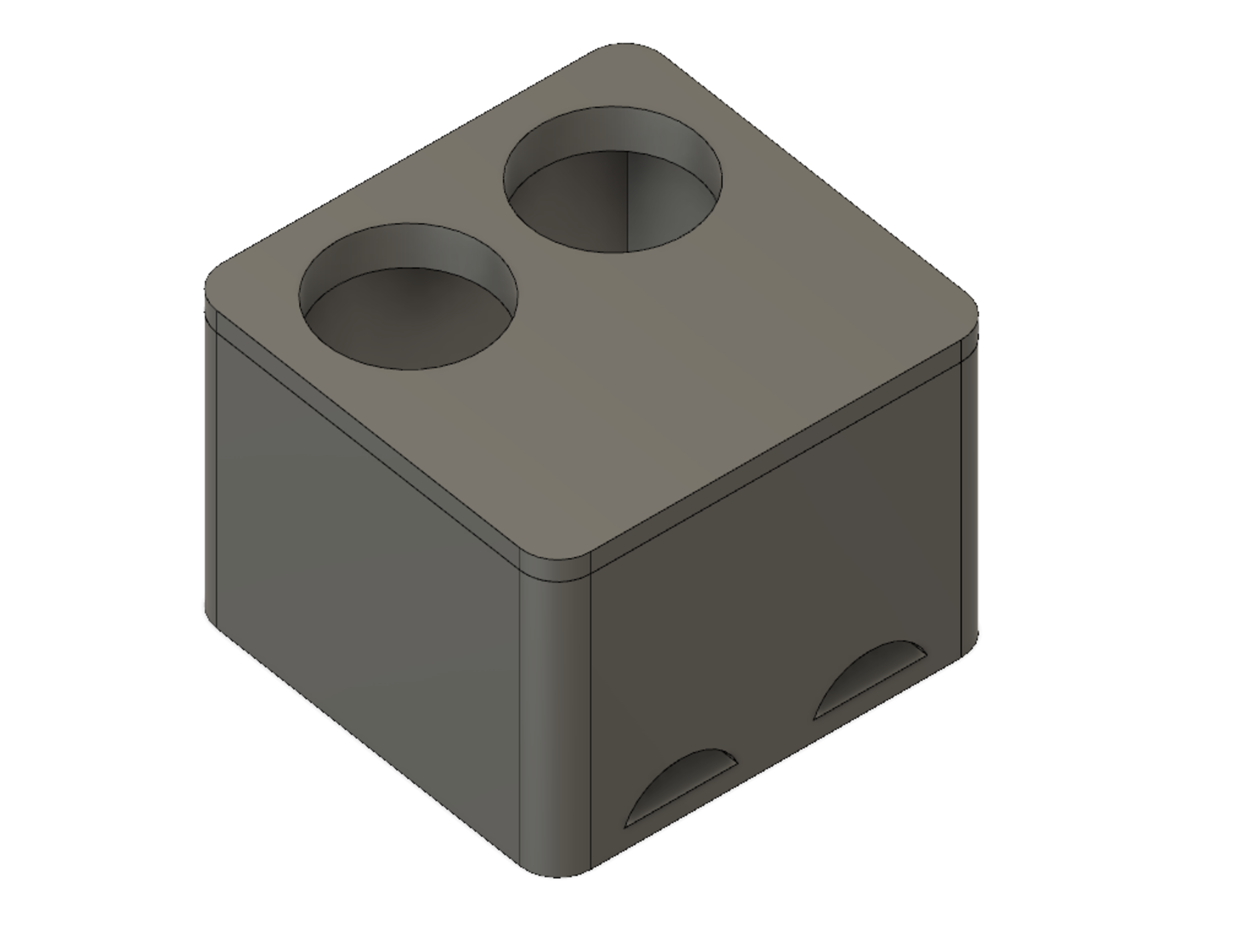
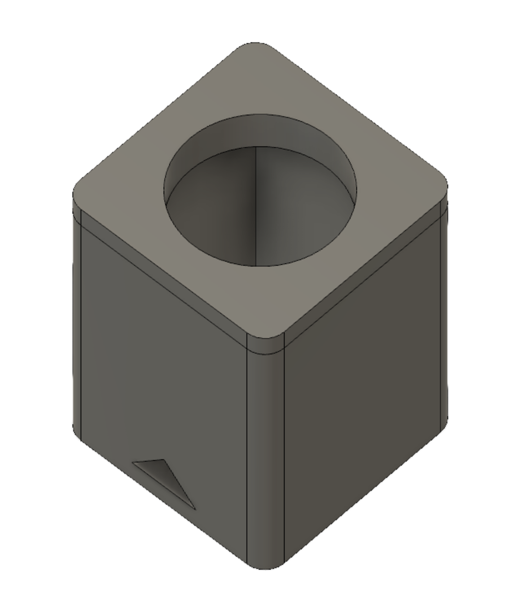
We mounted the boxes inside in the stables and so they didn’t need to be 100% waterproof just resistant to horse slobber! The lights themselves were mounted using the self adhesive strips that comes with the light and were reinforced using cable clips over the strip (being careful not to actually pinch the strip which could cause damage).
We then wired everything up (we used this wire https://www.screwfix.com/p/prysmian-6242y-twin-earth-cable-2-5mm-x-50m-grey/83956). Our wiring process for each set of lights went as follows (also see the diagram above):
To make working on the system easier we later wired up an isolator switch (something a bit like this https://www.amazon.co.uk/Techniks-BS01-Battery-Isolator-Switch/dp/B009CRM34I). This went between the positive load terminal and all the positive connections to the switches. This allowed us to use one switch to isolate the loads from the system (which is good if you need to do repairs or make changes).
At this point if everything has gone to plan it should be good to go! Flick the switches and you should have light!
Because we’re engineers at heart we love to track the performance of our system and collect data! We purchased a pair of Digital MultiMeters (https://www.amazon.co.uk/gp/product/B01JOUZELG). These allow us to measure voltage and current from which we can calculate the amount of power we’re generating/using. These work by connecting a ‘current shunt’ inline with the wiring we had. The first we connected to the solar panel to keep track of the power coming in. The second connects to the load output from the solar charge controller to measure the total amount of power being consumed by our lights.
We ran these for about a week and found that in our location with our setup we generated 240 watt hours from the solar panel (this is the amount of power from the panel that we were able to utilise and not necessarily the peak amount of power that could be generated).
We also found that we were consuming approximately 100 watt hours a week (this will of course vary greatly depending on your specific use but we were mucking out two horses for a frame of reference). This means that we are generating more than twice the amount of power than we’re using. We’re quite happy with this margin and it should mean this system operates smoothly going forward and will keep our battery healthy.
Below is a rough breakdown of the costs involved. These will change depending on your exact choices however it will give you a rough idea of costs.
| Item | Unit Price | Quantity | Line Price |
|---|---|---|---|
| Solar Panel Kit | 134.00 | 1 | 134.00 |
| Led Lights | 7.99 | 2 | 15.98 |
| Battery | FREE (Used an old car battery) | 1 | N/A |
| Switches (Pack of 8) | 5.99 | 1 | 5.99 |
| Digital Multimeter (Optional) | 12.39 | 2 | 24.78 |
| Wire (50 meters) | 32.48 | 1 | 32.48 |
| 3D Printed Boxes | Hard to quantify but about £0.50 each | 5 | 2.50 |
| Total | 216.73 |
The goal of this was never to save money but it’s interesting to do the sums to see when we would. At the time of writing (Dec’18 in the South East of UK) the price of electricity is £0.147 per kWH. This means that to recover our costs we’ll need to generate 1,474 kWH of electricity. At 200 watt hours a week this will take 7,370 weeks (141 years) to recover the cost. Clearly this isn’t a good idea if all you’re looking for is to save money on electricity. However if we consider the yearly standing fixed cost of £70.30 that would apply if we had a mains connection we would recover the costs in just over 3.5 years (and this doesn’t even consider the upfront costs of getting a mains connection to the yard if you didn’t have one).
We used information from https://www.nimblefins.co.uk/average-cost-electricity-kwh-uk for our average costs and standing fixed charge costs.
This system has been running for a couple of months now and they’ve been very happy with it. Being able to flick a switch and have the light has been a huge improvement over the collection of torches that were being used before. The next steps will be adding an inverter to allow low power 240 volt AC devices (the kind that plug into a standard UK wall socket) to be run from the system for short periods of time. This would, for example, allow clippers or a vet’s laptop to be plugged in.
If you’d be interested in finding out more about that leave a comment and let us know. We’re going to try and also update this post as changes are made to the system and more lessons are learnt.